
F28069的cpu定时器
创始人
2024-03-20 12:16:06
工程搭建参考:https://blog.csdn.net/feisy/article/details/126380289
F28069有三个32位的CPU定时器:0,1,2。0,1可用,如果程序未使用DIS/BIOS,定时器2也可用。
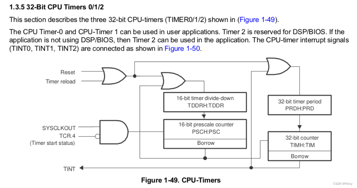
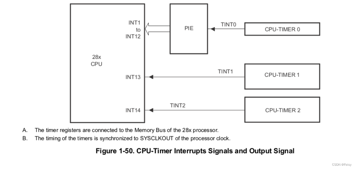
CPU定时器相关的有5个信号,四个输入信号,一个输出信号
- Reset信号:复位信号,给定时器复位用的
- Timer reload:定时器重载信号,控制定时器要不要重新装载周期计算器
- SYSCLKOUT:系统时钟信号
- TCR.4=TCR.bit.4.TSS:控制定时器计时开始或者停止
- TINT:输出信息,周期中断
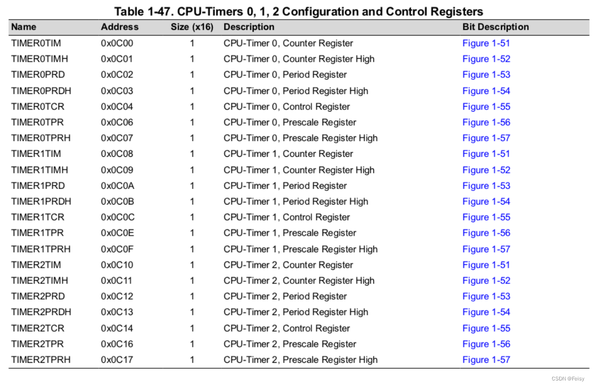
CPU定时器涉及的寄存器
- TDDR :定时器减一的时间长度,两个16位的寄存器表示
- PRD:设置CPU定时器的周期,两个16位的寄存器表示
- PSC开始计数时,会将TDDR 装载到这里,用来不断自减减到0,到0会产生TIMCLK信号,让TIM减一
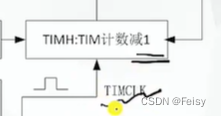
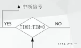
- TIM:开始计数时,会将PRD 装载到这里,用来不断自减,,会产生一个中断信号,这时会回调定时器中断函数
- TPR:F28069里跟TDDR功能一样的寄存器?
- TCR:装载,启用或者停止定时器的寄存器:TCR.bit.TSS = 1(1 = Stop timer, 0 = Start/Restart Timer),TCR.bit.TRB = 1( 1 = reload timer),TCR.bit.TIE = 1( 0 = Disable/ 1 = Enable Timer Interrupt)
定时器的寄存器的形式是XH:X这样的形式,后半部分X表示低位,前半部分XH表示高位
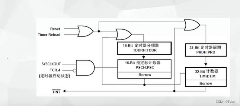
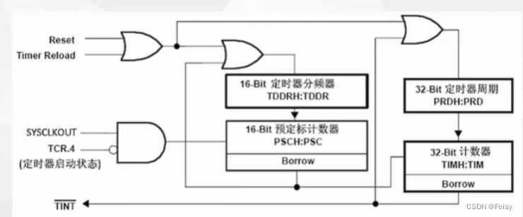
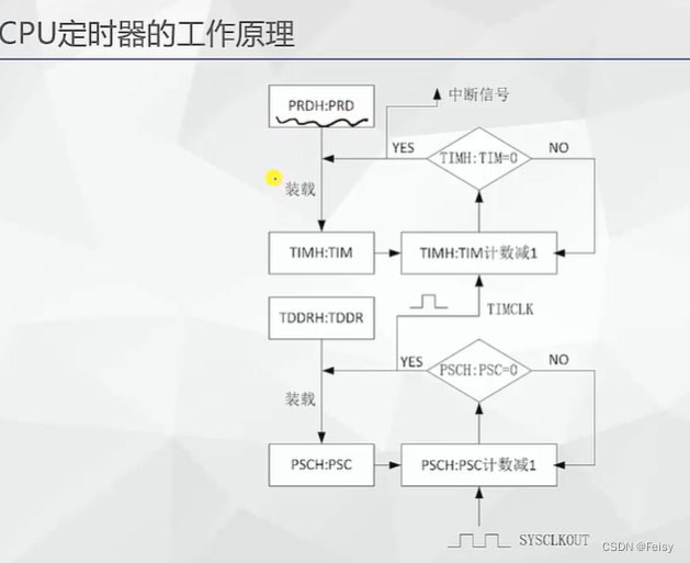
#CPU定时器的工作原理
-
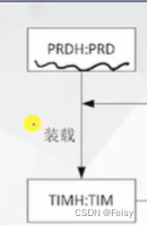
给CPU周期寄存器赋值

-
开始计数时,CPU会将计数值装在到TIM寄存器
-
每个一个TIMCLK,TIM会不断减一,一直减到0
-
减到0,完成一个定时周期,会产生一个中断
.
TIMCLK代表是了计数器减一的时间长度,它是通过定时器 的分频寄存器TDDR来设置的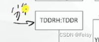
计数时,TIMCLK会被装载到PSC寄存器
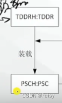
PSC里面的数值在每个SYSCLK都会减一,减到0时,会产生一个让TIMCLK减一的信号
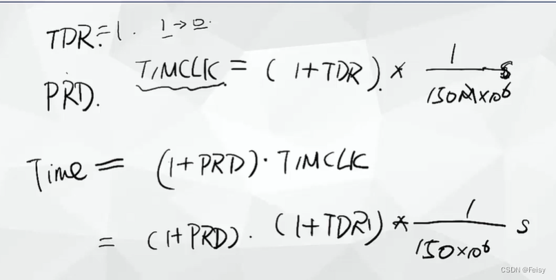
一个计算例子
PDR会被装载到PSC,每个SYSCLK都会减一,减到0时,会产生一个让TIMCLK减一的信号,TIMCLK=(1+PDR)个SYSCLKOUT,以F28335为例,主频是150M,TIMCLK=(1+PDR)*(1/150M)秒
一个周期是 (1+PRD) * TIMCLK
代码演示,通过定时器来控制LED闪烁
1 设置定时器的回调函数
注意,TINT0是在PIE TABLE的第7位,后面还有关于启用第一组,以及启用第7个中断的设置
// Interrupts that are used in this example are re-mapped to
// ISR functions found within this file.EALLOW;  // This is needed to write to EALLOW protected registersPieVectTable.TINT0 = &cpu_timer0_isr;EDIS;    // This is needed to disable write to EALLOW protected registers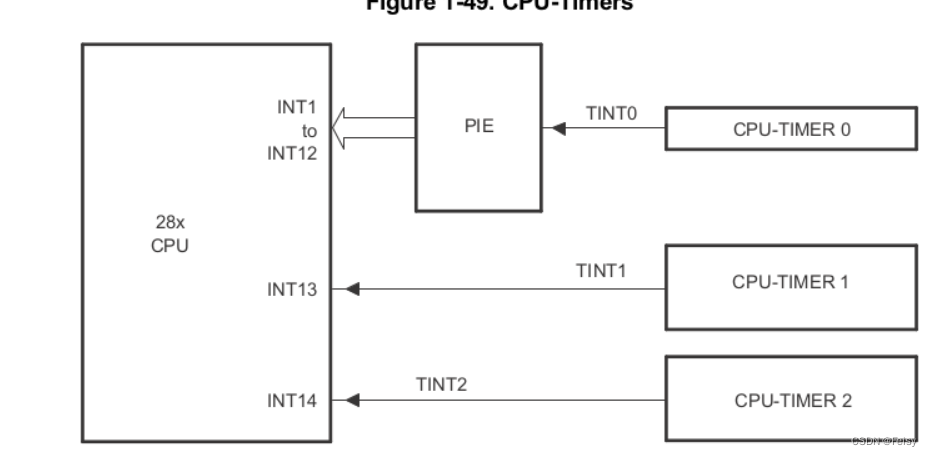
2 获取定时器寄存器, 配置定时器的一些默认值
使用到的一个函数
void InitCpuTimers(void)
{// CPU Timer 0// Initialize address pointers to respective timer registers:CpuTimer0.RegsAddr = &CpuTimer0Regs;// Initialize timer period to maximum:CpuTimer0Regs.PRD.all  = 0xFFFFFFFF;//PRD寄存器设置CPU定时器的周期,两个16位的寄存器表示,这里设置到最大//TPR寄存器的作用是CPU会在(TPR[TDDRH:TDDR]+1)个SYSCLOUT后,将TIM减一,这里置0,表示,每个SYSCLKOUT都会让TIM减一// Initialize pre-scale counter to divide by 1 (SYSCLKOUT)://The 32-bit counter register TIMH:TIM is loaded with//the value in the period register PRDH:PRD. The counter decrements once every (TPR[TDDRH:TDDR]+1)SYSCLKOUT cycles, where TDDRH:TDDR is the timer divider. CpuTimer0Regs.TPR.all  = 0;CpuTimer0Regs.TPRH.all = 0;// Make sure timer is stopped:CpuTimer0Regs.TCR.bit.TSS = 1;//TSS=0表示定时器停止// Reload all counter register with period value:CpuTimer0Regs.TCR.bit.TRB = 1;// Reset interrupt counters://CpuTimer0.InterruptCount = 0;// Initialize address pointers to respective timer registers:CpuTimer1.RegsAddr = &CpuTimer1Regs;CpuTimer2.RegsAddr = &CpuTimer2Regs;// Initialize timer period to maximum:CpuTimer1Regs.PRD.all  = 0xFFFFFFFF;CpuTimer2Regs.PRD.all  = 0xFFFFFFFF;// Initialize pre-scale counter to divide by 1 (SYSCLKOUT):CpuTimer1Regs.TPR.all  = 0;CpuTimer1Regs.TPRH.all = 0;CpuTimer2Regs.TPR.all  = 0;CpuTimer2Regs.TPRH.all = 0;// Make sure timers are stopped:CpuTimer1Regs.TCR.bit.TSS = 1;CpuTimer2Regs.TCR.bit.TSS = 1;// Reload all counter register with period value:CpuTimer1Regs.TCR.bit.TRB = 1;CpuTimer2Regs.TCR.bit.TRB = 1;// Reset interrupt counters://CpuTimer1.InterruptCount = 0;//CpuTimer2.InterruptCount = 0;}
3 设置定时器的长度
因为F28069的主频是80M,所以我们设置定时器的周期步数是80,每一步是1000000,即1000000个SYSCLKOUT,定时器减一。
// Configure CPU-Timer 0, 1, and 2 to interrupt every second:
// 80MHz CPU Freq, 1 second Period (in uSeconds)ConfigCpuTimer(&CpuTimer0, 80, 1000000);
void ConfigCpuTimer(struct CPUTIMER_VARS *Timer, float Freq, float Period)
{Uint32 	PeriodInClocks;// Initialize timer period:Timer->CPUFreqInMHz = Freq;Timer->PeriodInUSec = Period;PeriodInClocks = (long) (Freq * Period);//设置CPU定时器的周期,Timer->RegsAddr->PRD.all = PeriodInClocks - 1; // Counter decrements PRD+1 times each period//这里这样的设置是每个SYSCLKOUT,都会产生一个TIMCLK,让其减一// Set pre-scale counter to divide by 1 (SYSCLKOUT):Timer->RegsAddr->TPR.all  = 0;Timer->RegsAddr->TPRH.all  = 0;// Initialize timer control register:Timer->RegsAddr->TCR.bit.TSS = 1;      // 1 = Stop timer, 0 = Start/Restart TimerTimer->RegsAddr->TCR.bit.TRB = 1;      // 1 = reload timerTimer->RegsAddr->TCR.bit.SOFT = 0;Timer->RegsAddr->TCR.bit.FREE = 0;     // Timer Free Run DisabledTimer->RegsAddr->TCR.bit.TIE = 1;      // 0 = Disable/ 1 = Enable Timer Interrupt// Reset interrupt counter:Timer->InterruptCount = 0;}
4 启用定时器
//TCR.bit.TSS = 0表示启动寄存器CpuTimer0Regs.TCR.all = 0x4000; // Use write-only instruction to set TSS bit = 0
5 启用 中断向量表的第一组
//// Enable CPU INT1 which is connected to CPU-Timer 0//IER |= M_INT1;
6 启用 中断向量表的第一组的第7个中断
//// Enable TINT0 in the PIE: Group 1 interrupt 7//PieCtrlRegs.PIEIER1.bit.INTx7 = 1;
7 打开全局中断
// Enable global Interrupts and higher priority real-time debug events:EINT; // Enable Global interrupt INTMERTM; // Enable Global realtime interrupt DBGM
5 完整代码
//###########################################################################
//
// FILE:   Example_2806xLEDBlink.c
//
// TITLE:  Timer based blinking LED Example
//
//!  \addtogroup f2806x_example_list
//!  Timer based blinking LED(timed_led_blink)
//!
//!  This example configures CPU Timer0 for a 500 msec period, and toggles the
//!  GPIO34 LED once per interrupt. For testing purposes, this example
//!  also increments a counter each time the timer asserts an interrupt.
//!
//!  \b Watch \b Variables \n
//!  - CpuTimer0.InterruptCount
//!
//! \b External \b Connections \n
//!  Monitor the GPIO34 LED blink on (for 500 msec) and off (for 500 msec) on
//!  the 2806x control card.
//
//###########################################################################
// $TI Release:  $
// $Release Date:  $
// $Copyright:
// Copyright (C) 2009-2022 Texas Instruments Incorporated - http://www.ti.com/
//
// Redistribution and use in source and binary forms, with or without
// modification, are permitted provided that the following conditions
// are met:
//
//   Redistributions of source code must retain the above copyright
//   notice, this list of conditions and the following disclaimer.
//
//   Redistributions in binary form must reproduce the above copyright
//   notice, this list of conditions and the following disclaimer in the
//   documentation and/or other materials provided with the
//   distribution.
//
//   Neither the name of Texas Instruments Incorporated nor the names of
//   its contributors may be used to endorse or promote products derived
//   from this software without specific prior written permission.
//
// THIS SOFTWARE IS PROVIDED BY THE COPYRIGHT HOLDERS AND CONTRIBUTORS
// "AS IS" AND ANY EXPRESS OR IMPLIED WARRANTIES, INCLUDING, BUT NOT
// LIMITED TO, THE IMPLIED WARRANTIES OF MERCHANTABILITY AND FITNESS FOR
// A PARTICULAR PURPOSE ARE DISCLAIMED. IN NO EVENT SHALL THE COPYRIGHT
// OWNER OR CONTRIBUTORS BE LIABLE FOR ANY DIRECT, INDIRECT, INCIDENTAL,
// SPECIAL, EXEMPLARY, OR CONSEQUENTIAL DAMAGES (INCLUDING, BUT NOT
// LIMITED TO, PROCUREMENT OF SUBSTITUTE GOODS OR SERVICES; LOSS OF USE,
// DATA, OR PROFITS; OR BUSINESS INTERRUPTION) HOWEVER CAUSED AND ON ANY
// THEORY OF LIABILITY, WHETHER IN CONTRACT, STRICT LIABILITY, OR TORT
// (INCLUDING NEGLIGENCE OR OTHERWISE) ARISING IN ANY WAY OUT OF THE USE
// OF THIS SOFTWARE, EVEN IF ADVISED OF THE POSSIBILITY OF SUCH DAMAGE.
// $
//###########################################################################//
// Included Files
//
#include "DSP28x_Project.h"     // Device Headerfile and Examples Include File//
// Function Prototypes statements for functions found within this file.
//
__interrupt void cpu_timer0_isr(void);//
// Main
//
void main(void)
{//// Step 1. Initialize System Control:// PLL, WatchDog, enable Peripheral Clocks// This example function is found in the F2806x_SysCtrl.c file.//InitSysCtrl();//// Step 2. Initalize GPIO:// This example function is found in the F2806x_Gpio.c file and// illustrates how to set the GPIO to it's default state.//
//    InitGpio();  // Skipped for this example//// Step 3. Clear all interrupts and initialize PIE vector table:// Disable CPU interrupts//DINT;//// Initialize the PIE control registers to their default state.// The default state is all PIE interrupts disabled and flags// are cleared.// This function is found in the F2806x_PieCtrl.c file.//InitPieCtrl();//// Disable CPU interrupts and clear all CPU interrupt flags//IER = 0x0000;IFR = 0x0000;//// Initialize the PIE vector table with pointers to the shell Interrupt// Service Routines (ISR).// This will populate the entire table, even if the interrupt// is not used in this example.  This is useful for debug purposes.// The shell ISR routines are found in F2806x_DefaultIsr.c.// This function is found in F2806x_PieVect.c.//InitPieVectTable();//// Interrupts that are used in this example are re-mapped to// ISR functions found within this file.//EALLOW;    // This is needed to write to EALLOW protected registersPieVectTable.TINT0 = &cpu_timer0_isr;EDIS;      // This is needed to disable write to EALLOW protected registers//// Step 4. Initialize the Device Peripheral. This function can be//         found in F2806x_CpuTimers.c//InitCpuTimers();   // For this example, only initialize the Cpu Timers//// Configure CPU-Timer 0 to interrupt every 500 milliseconds:// 80MHz CPU Freq, 50 millisecond Period (in uSeconds)//ConfigCpuTimer(&CpuTimer0, 80, 500000);//// To ensure precise timing, use write-only instructions to write to the// entire register. Therefore, if any of the configuration bits are changed// in ConfigCpuTimer and InitCpuTimers (in F2806x_CpuTimers.h), the// below settings must also be updated.////// Use write-only instruction to set TSS bit = 0//CpuTimer0Regs.TCR.all = 0x4001;//// Step 5. User specific code, enable interrupts:////// Configure GPIO34 as a GPIO output pin//EALLOW;GpioCtrlRegs.GPBMUX1.bit.GPIO34 = 0;GpioCtrlRegs.GPBDIR.bit.GPIO34 = 1;EDIS;//// Enable CPU INT1 which is connected to CPU-Timer 0//IER |= M_INT1;//// Enable TINT0 in the PIE: Group 1 interrupt 7//PieCtrlRegs.PIEIER1.bit.INTx7 = 1;//// Enable global Interrupts and higher priority real-time debug events//EINT;   // Enable Global interrupt INTMERTM;   // Enable Global realtime interrupt DBGM//// Step 6. IDLE loop. Just sit and loop forever (optional)//for(;;);
}//
// cpu_timer0_isr -
//
__interrupt void
cpu_timer0_isr(void)
{CpuTimer0.InterruptCount++;//// Toggle GPIO34 once per 500 milliseconds////我之前一直用软件的角度去看代码,以为这个是赋值的意思,但其实这个是硬件中的GPIO的翻转操作//,即每次=1,会让GPIO的电平发生变化,变到另外一个状态。//比如,原先是高电平,执行一次=1,就变成了低电平了。。。。GpioDataRegs.GPBTOGGLE.bit.GPIO34 = 1;//// Acknowledge this interrupt to receive more interrupts from group 1//PieCtrlRegs.PIEACK.all = PIEACK_GROUP1;
}//
// End of File
//相关内容
热门资讯
埃菲尔铁塔在哪 中国仿建埃菲尔...
2019年4月26日,广西南宁市,街头惊现一座巨型山寨版埃菲尔铁塔,高约20米,白色塔身,造型逼真,...
苗族的传统节日 贵州苗族节日有...
【岜沙苗族芦笙节】岜沙,苗语叫“分送”,距从江县城7.5公里,是世界上最崇拜树木并以树为神的枪手部落...
北京的名胜古迹 北京最著名的景...
北京从元代开始,逐渐走上帝国首都的道路,先是成为大辽朝五大首都之一的南京城,随着金灭辽,金代从海陵王...
长白山自助游攻略 吉林长白山游...
昨天介绍了西坡的景点详细请看链接:一个人的旅行,据说能看到长白山天池全凭运气,您的运气如何?今日介绍...
应用未安装解决办法 平板应用未...
---IT小技术,每天Get一个小技能!一、前言描述苹果IPad2居然不能安装怎么办?与此IPad不...
脚上的穴位图 脚面经络图对应的...
人体穴位作用图解大全更清晰直观的标注了各个人体穴位的作用,包括头部穴位图、胸部穴位图、背部穴位图、胳...
世界上最漂亮的人 世界上最漂亮...
此前在某网上,选出了全球265万颜值姣好的女性。从这些数量庞大的女性群体中,人们投票选出了心目中最美...
猫咪吃了塑料袋怎么办 猫咪误食...
你知道吗?塑料袋放久了会长猫哦!要说猫咪对塑料袋的喜爱程度完完全全可以媲美纸箱家里只要一有塑料袋的响...
demo什么意思 demo版本...
618快到了,各位的小金库大概也在准备开闸放水了吧。没有小金库的,也该向老婆撒娇卖萌服个软了,一切只...
埃菲尔铁塔在哪 中国仿建埃菲尔...
2019年4月26日,广西南宁市,街头惊现一座巨型山寨版埃菲尔铁塔,高约20米,白色塔身,造型逼真,...
苗族的传统节日 贵州苗族节日有...
【岜沙苗族芦笙节】岜沙,苗语叫“分送”,距从江县城7.5公里,是世界上最崇拜树木并以树为神的枪手部落...
北京的名胜古迹 北京最著名的景...
北京从元代开始,逐渐走上帝国首都的道路,先是成为大辽朝五大首都之一的南京城,随着金灭辽,金代从海陵王...
长白山自助游攻略 吉林长白山游...
昨天介绍了西坡的景点详细请看链接:一个人的旅行,据说能看到长白山天池全凭运气,您的运气如何?今日介绍...